- 您现在的位置:买卖IC网 > Sheet目录3861 > PIC18F44J50-I/ML (Microchip Technology)IC PIC MCU FLASH 16K 2V 44-QFN
PIC18F2XJXX/4XJXX FAMILY
DS39687E-page 14
2009 Microchip Technology Inc.
3.2.1
MODIFYING CODE MEMORY
The previous programming example assumed that the
device had been Bulk Erased prior to programming. It
may be the case, however, that the user wishes to
modify only a section of an already programmed device.
The appropriate number of bytes required for the erase
buffer must be read out of code memory (as described
tion Word”) and buffered. Modifications can be made
on this buffer. Then, the block of code memory that was
read out must be erased and rewritten with the
modified data. The code sequence is shown in
The WREN bit must be set if the WR bit in EECON1 is
used to initiate a write sequence.
3.2.2
CONFIGURATION WORD
PROGRAMMING
Since the Flash Configuration Words are stored in
program memory, they are programmed as if they were
program data. Refer to Section 3.2 “Code Memory
Memory” for methods and examples on programming
or modifying program memory. See also Section 5.0
“Configuration Word” for additional information on
the Configuration Words.
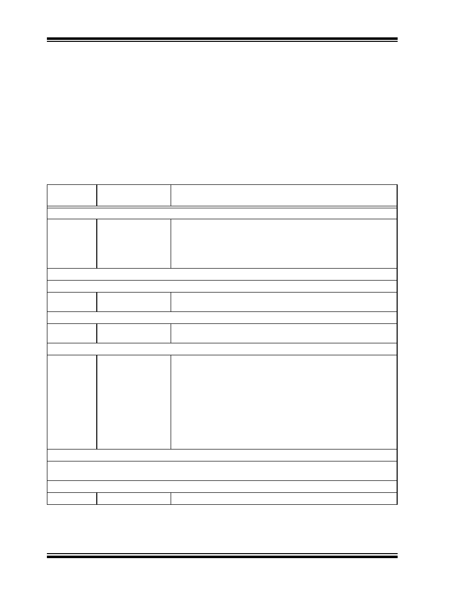
TABLE 3-4:
MODIFYING CODE MEMORY
4-Bit
Command
Data Payload
Core Instruction
Step 1: Set the Table Pointer for the block to be erased.
0000
0E <Addr[21:16]>
6E F8
0E <Addr[8:15]>
6E F7
0E <Addr[7:0]>
6E F6
MOVLW
<Addr[21:16]>
MOVWF
TBLPTRU
MOVLW
<Addr[8:15]>
MOVWF
TBLPTRH
MOVLW
<Addr[7:0]>
MOVWF
TBLPTRL
Step 2: Read and modify code memory (see Section 4.1 “Read Code Memory”).
Step 3: Enable memory writes and set up an erase.
0000
84 A6
88 A6
BSF
EECON1, WREN
BSF
EECON1, FREE
Step 4: Initiate erase.
0000
82 A6
00 00
BSF
EECON1, WR
NOP - hold PGC high for time P10.
Step 5: Load write buffer. The correct bytes will be selected based on the Table Pointer.
0000
1101
.
1111
0000
0E <Addr[21:16]>
6E F8
0E <Addr[8:15]>
6E F7
0E <Addr[7:0]>
6E F6
<MSB><LSB>
.
<MSB><LSB>
00 00
MOVLW
<Addr[21:16]>
MOVWF
TBLPTRU
MOVLW
<Addr[8:15]>
MOVWF
TBLPTRH
MOVLW
<Addr[7:0]>
MOVWF
TBLPTRL
Write 2 bytes and post-increment address by 2.
Repeat write operation 30 more times to fill the write buffer
Write 2 bytes and start programming.
NOP - hold PGC high for time P9.
Step 6: Repeat Step 5 for a total of 16 times (if rewriting the entire 1024 bytes of the erase page size).
Step 7: To continue modifying data, repeat Steps 1 through 5, where the Address Pointer is incremented by 1024 bytes at each
iteration of the loop.
Step 8: Disable writes.
0000
94 A6
BCF
EECON1, WREN
发布紧急采购,3分钟左右您将得到回复。
相关PDF资料
PIC18LF26J50-I/SS
IC PIC MCU FLASH 64K 2V 28-SSOP
SFW19R-2STE1
SFW19R-2STE1-FFC/FPC CONN
HFW30R-2STE1
HFW30R-2STE1-FFC/FPC CONN
PIC18LF44J50-I/ML
IC PIC MCU FLASH 16K 2V 44-QFN
AT90S1200-12PI
IC MCU 1K FLSH 12MHZ IT 20DIP
AT90S1200-12PC
IC MCU 1K FLSH 12MHZ 20DIP
PIC16LF87-I/SO
IC MCU FLASH 4KX14 EEPROM 18SOIC
AT90LS8535-4AI
IC MCU 8K 4MHZ A/D LV IT 44TQFP
相关代理商/技术参数
PIC18F44J50-I/PT
功能描述:8位微控制器 -MCU Full Spd USB 16KB 4KBRAM nanoWatt
RoHS:否 制造商:Silicon Labs 核心:8051 处理器系列:C8051F39x 数据总线宽度:8 bit 最大时钟频率:50 MHz 程序存储器大小:16 KB 数据 RAM 大小:1 KB 片上 ADC:Yes 工作电源电压:1.8 V to 3.6 V 工作温度范围:- 40 C to + 105 C 封装 / 箱体:QFN-20 安装风格:SMD/SMT
PIC18F44J50T-I/ML
功能描述:8位微控制器 -MCU Full Spd USB 16KB 4KBRAM nanoWatt RoHS:否 制造商:Silicon Labs 核心:8051 处理器系列:C8051F39x 数据总线宽度:8 bit 最大时钟频率:50 MHz 程序存储器大小:16 KB 数据 RAM 大小:1 KB 片上 ADC:Yes 工作电源电压:1.8 V to 3.6 V 工作温度范围:- 40 C to + 105 C 封装 / 箱体:QFN-20 安装风格:SMD/SMT
PIC18F44J50T-I/PT
功能描述:8位微控制器 -MCU Full Spd USB 16KB 4KBRAM nanoWatt RoHS:否 制造商:Silicon Labs 核心:8051 处理器系列:C8051F39x 数据总线宽度:8 bit 最大时钟频率:50 MHz 程序存储器大小:16 KB 数据 RAM 大小:1 KB 片上 ADC:Yes 工作电源电压:1.8 V to 3.6 V 工作温度范围:- 40 C to + 105 C 封装 / 箱体:QFN-20 安装风格:SMD/SMT
PIC18F44K20-E/ML
功能描述:8位微控制器 -MCU 16KB Flash 768B RAM 36 I/O 8B RoHS:否 制造商:Silicon Labs 核心:8051 处理器系列:C8051F39x 数据总线宽度:8 bit 最大时钟频率:50 MHz 程序存储器大小:16 KB 数据 RAM 大小:1 KB 片上 ADC:Yes 工作电源电压:1.8 V to 3.6 V 工作温度范围:- 40 C to + 105 C 封装 / 箱体:QFN-20 安装风格:SMD/SMT
PIC18F44K20-E/MV
功能描述:8位微控制器 -MCU 16KB FL 768b-RAM 8b Familynanowatt XLP
RoHS:否 制造商:Silicon Labs 核心:8051 处理器系列:C8051F39x 数据总线宽度:8 bit 最大时钟频率:50 MHz 程序存储器大小:16 KB 数据 RAM 大小:1 KB 片上 ADC:Yes 工作电源电压:1.8 V to 3.6 V 工作温度范围:- 40 C to + 105 C 封装 / 箱体:QFN-20 安装风格:SMD/SMT
PIC18F44K20-E/P
功能描述:8位微控制器 -MCU 16KB Flash 768B RAM 36 I/O 8B RoHS:否 制造商:Silicon Labs 核心:8051 处理器系列:C8051F39x 数据总线宽度:8 bit 最大时钟频率:50 MHz 程序存储器大小:16 KB 数据 RAM 大小:1 KB 片上 ADC:Yes 工作电源电压:1.8 V to 3.6 V 工作温度范围:- 40 C to + 105 C 封装 / 箱体:QFN-20 安装风格:SMD/SMT
PIC18F44K20-E/PT
功能描述:8位微控制器 -MCU 16KB Flash 768B RAM 36 I/O 8B
RoHS:否 制造商:Silicon Labs 核心:8051 处理器系列:C8051F39x 数据总线宽度:8 bit 最大时钟频率:50 MHz 程序存储器大小:16 KB 数据 RAM 大小:1 KB 片上 ADC:Yes 工作电源电压:1.8 V to 3.6 V 工作温度范围:- 40 C to + 105 C 封装 / 箱体:QFN-20 安装风格:SMD/SMT
PIC18F44K20-I/ML
功能描述:8位微控制器 -MCU 16KB Flash 768B RAM 36 I/O 8B RoHS:否 制造商:Silicon Labs 核心:8051 处理器系列:C8051F39x 数据总线宽度:8 bit 最大时钟频率:50 MHz 程序存储器大小:16 KB 数据 RAM 大小:1 KB 片上 ADC:Yes 工作电源电压:1.8 V to 3.6 V 工作温度范围:- 40 C to + 105 C 封装 / 箱体:QFN-20 安装风格:SMD/SMT